Nand Gate Schematic Diagram
Cmos implementation of a nand gate. Nand gate circuit diagram circuits inputs input through pull down electronic explanation button connected then power Nand gate nmos logic transistor schematic using digital universal ic symbols its two given below
NAND Gate Circuit Diagram and Working Explanation
Conversion of nand gate to basic gates Nand cmos logic implementation integrated lab4sys Nand gate
Scavenger's blog: nand gate
Circuit nand gate basic question does very work analysisCircuit analysis Gate nand using cmos wikipedia transistors gates logic diagram schematic electrical wiki fileSolved: chapter 7 problem 63p solution.
Nand logic tutorialspoint vlsi combinational circuitsGate nor nand equivalent logic circuit Nand gates basic circuit electronic5 schematic diagram of implementation of basic gates using nand gate.

Nand input
Nand gate schematic diagramDigital logic nand gate(universal gate),its symbols & schematics Schematic diagram of 2 input nand gateNand gate make schematic circuit electrical circuitlab created using.
Nand gate circuit diagram and working explanationUsing transistors as logic gates Digital logicNand gate schematic diagram input nor xor two wiring gates lab.

Nand gate using use scavenger
.
.


NAND Gate Circuit Diagram and Working Explanation

Digital Logic NAND Gate(Universal Gate),Its Symbols & Schematics

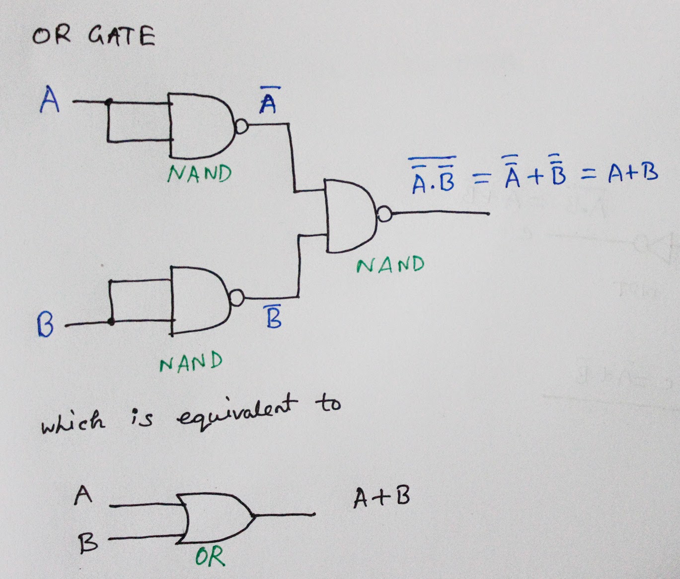
5 Schematic diagram of implementation of basic gates using NAND gate

nand gate schematic diagram - Style Guru: Fashion, Glitz, Glamour

Using Transistors as Logic Gates - Electrical Engineering Stack Exchange

Conversion of NAND gate to Basic gates
Scavenger's Blog: NAND Gate

digital logic - How to make a NAND Gate? - Electrical Engineering Stack

Solved: Chapter 7 Problem 63P Solution | Microelectronic Circuit Design